
Making a 1U Crossfader
I've been trying to finish up the last row (er, row and a third) of a eurorack drum machine for a long while now. The other week I finally got the actual case and racked&routed everything up.
The machine is itself is based around an 8-channel gate "bus," which is really all to say that it's built for triggering 8 simultaneous drum sounds. These are by default allocated to Kick, Snare, Hat (closed), Hat (open), Tom 1, Tom2, Clap, Cymbal using the wonderful drum modules from WMD and Erica.
Speaking of Erica, when they released the Perkons Voice I got the GAS (Gear Acquisition Syndrome) bad. Still haven't picked one up but I loved the sounds of the Perkons Drums machine and this would be an awesome way to get the sound into my own workflow.....I was worried about how it would fit into the signal path of my drum machine though. I had the actual room in the case to fit it but how could/should I incorporate it into the actual signal flow since all 8 of my gates were currently spoken for?
The way I saw it, I had a couple options:
- do nothing, and just manually re-patch the Perkons Voice in as I need it (un-patching another drum in the bus)
- build or buy a little switch so that the Perkons Voice could be swappable with a single voice easily (e.g, flip a switch and the gate that was triggering the Snare is now triggering Perkons Voice)
- build or buy a couple little crossfaders so that I could "inject" the Perkons Voice into the signal path of another drum and fade between them
I liked the last option the best even though it involved building or acquiring more modules. What it does allow is for the Perkons Voice to either be blended with a voice or replace it...but for it to work best every drum voice that I might want to blend with the Perkons would need a crossfader placed after it.
To save on costs I figured I'd build them myself, then I looked at PCB prices with current economic uncertainty and tariffs. Untenable.
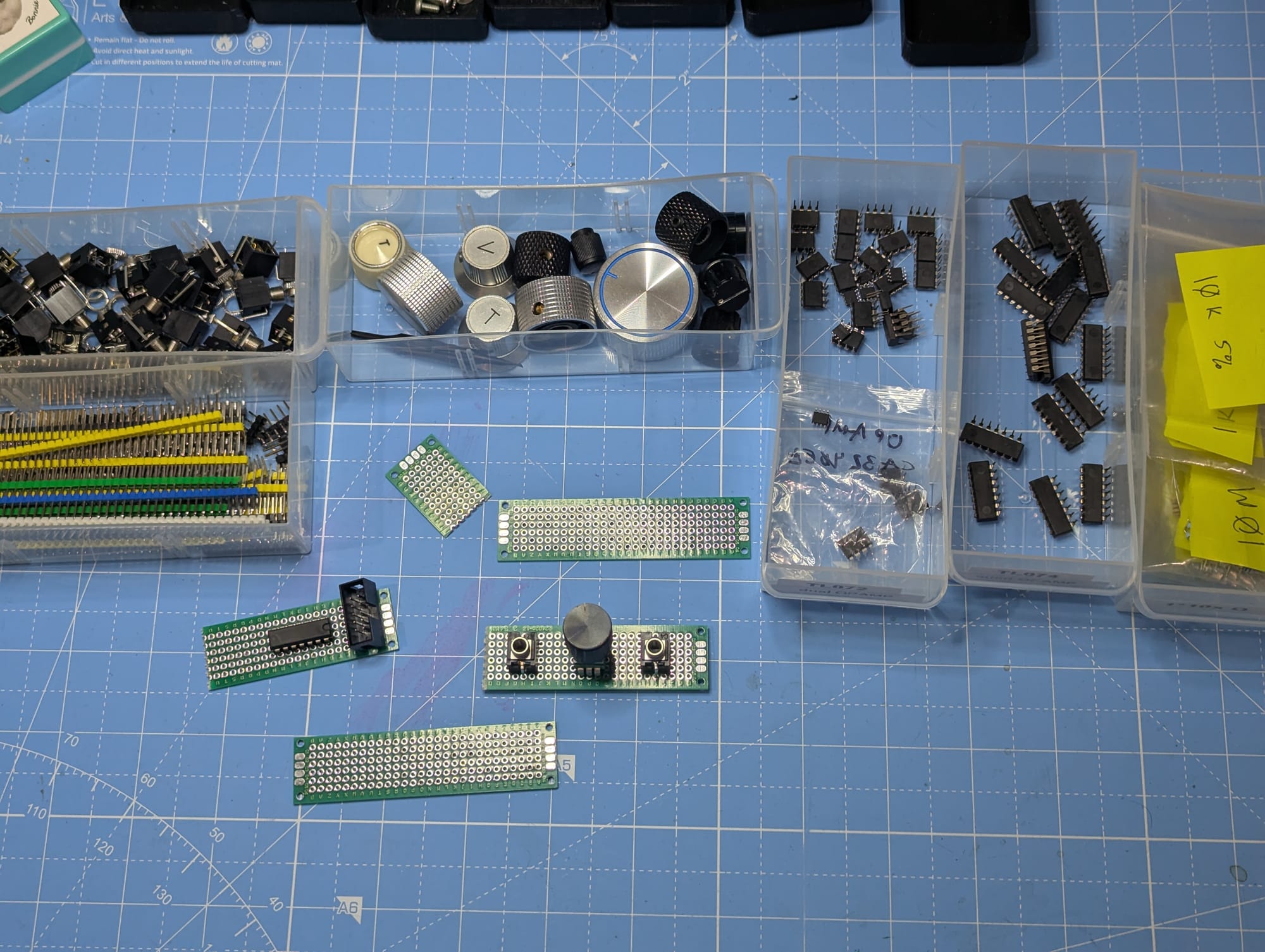
So to save further I decided I'd just use some protoboard and 3D print a shitty face plate, hoping I could scrounge the parts I needed from what I already had in the bins. Let's get started!
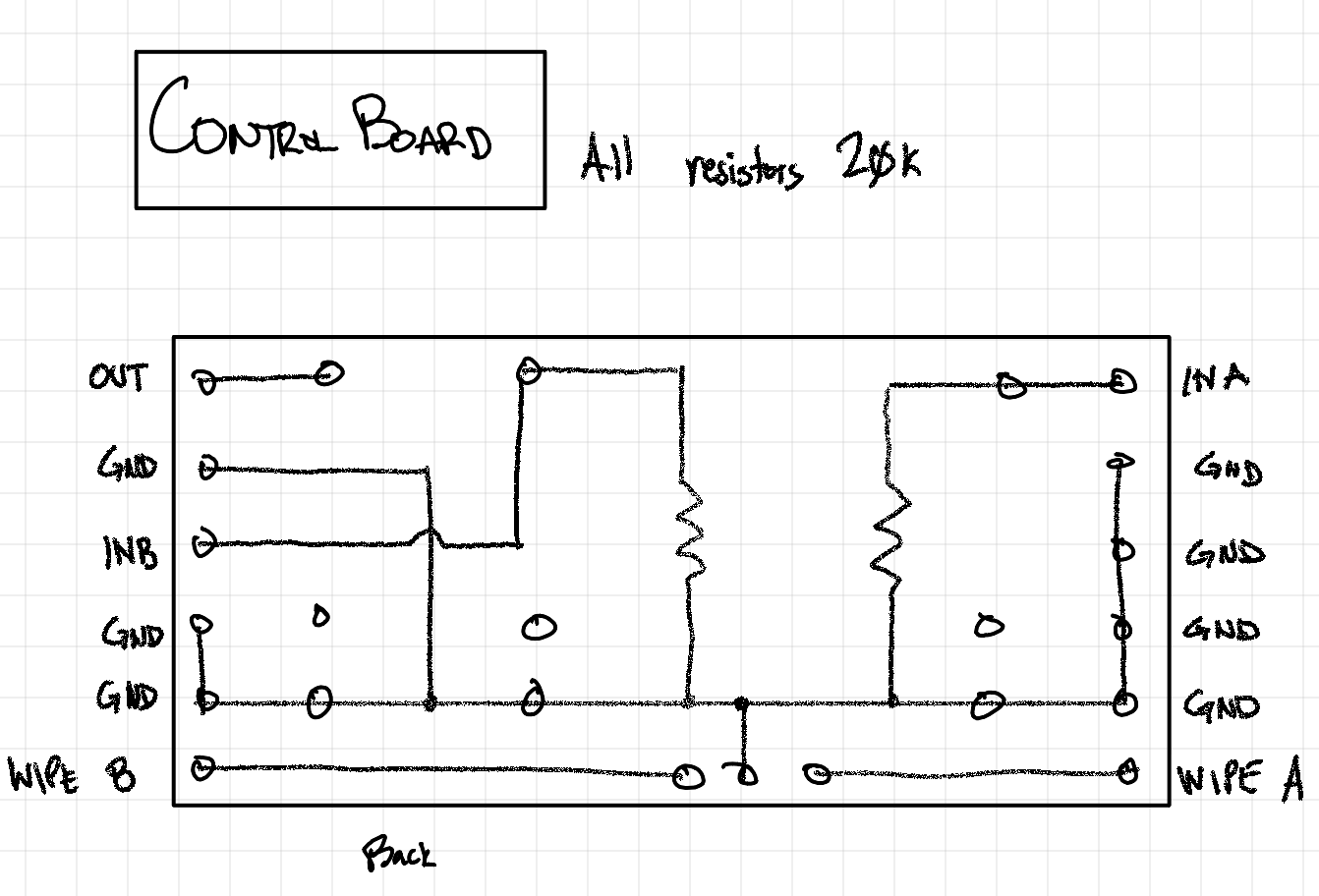
Starting off I used this Instructables by ozerik as a schematic reference
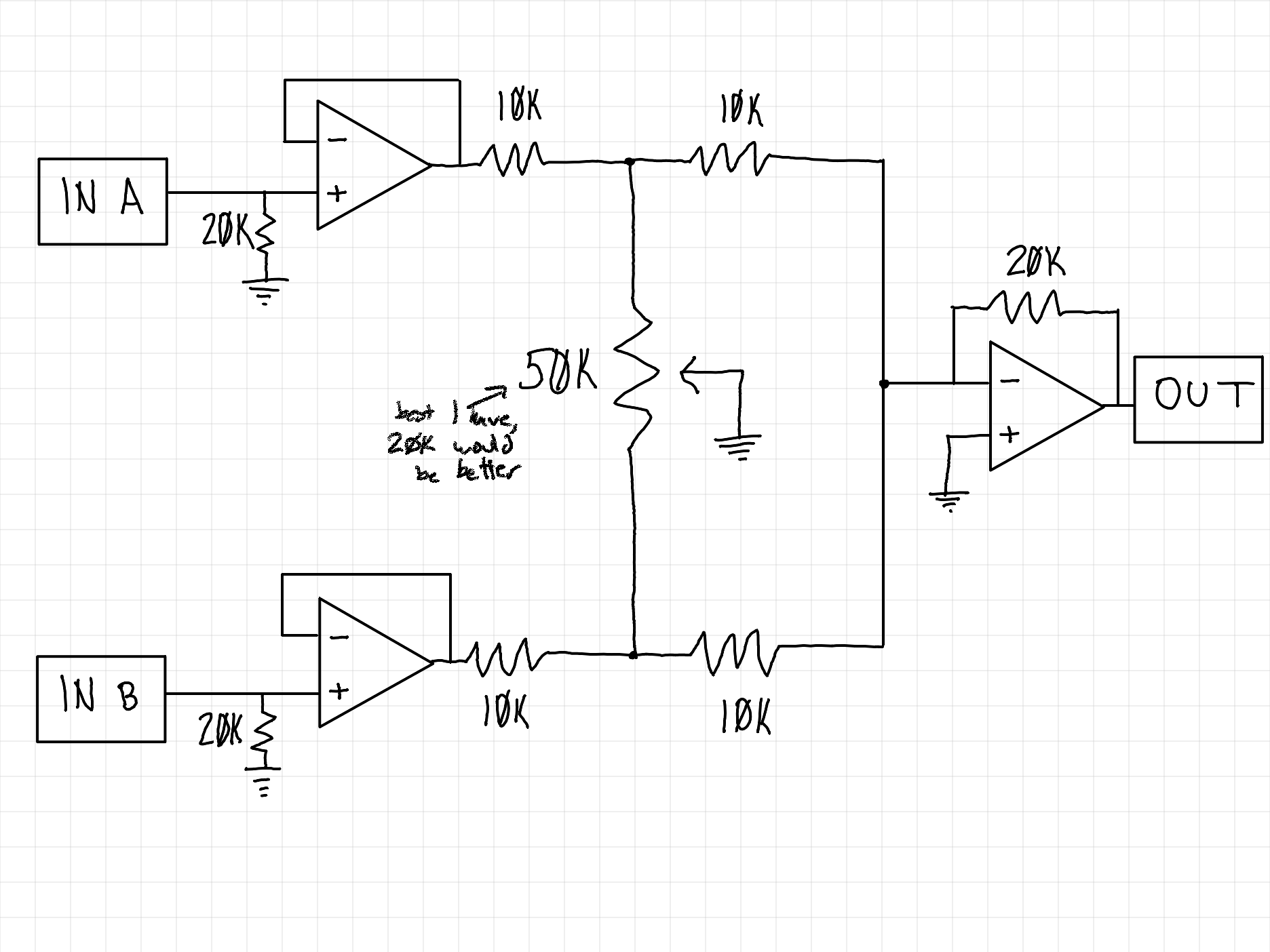
This'll work well for the intended application; it does invert the signal which is fine for audio but if we were using this to mix control voltage it would obviously not be ideal. I also only had a 50k pot lying around so I had to go with that instead of something like 20k which probably would have been better. Otherwise I had the parts!
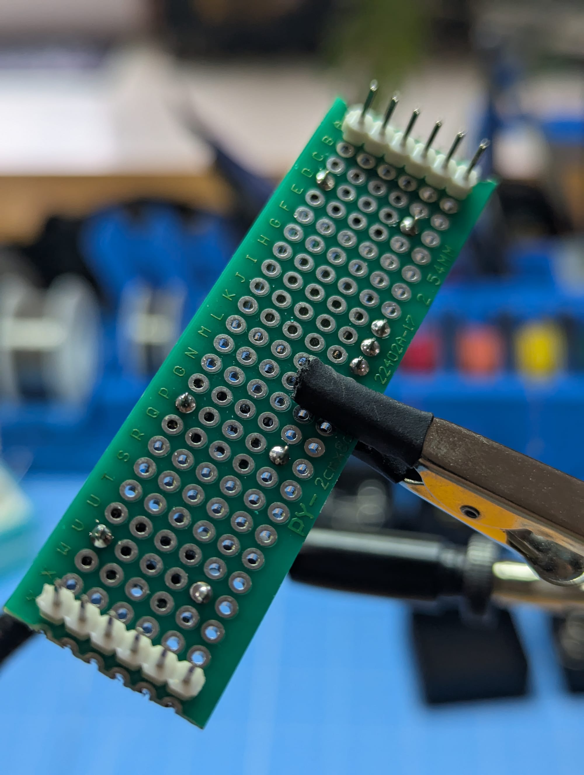
I was going to make this a 1U module which means the PCB can't be taller than 22.5mm. First thing to do was try and figure out how to fit everything in that size
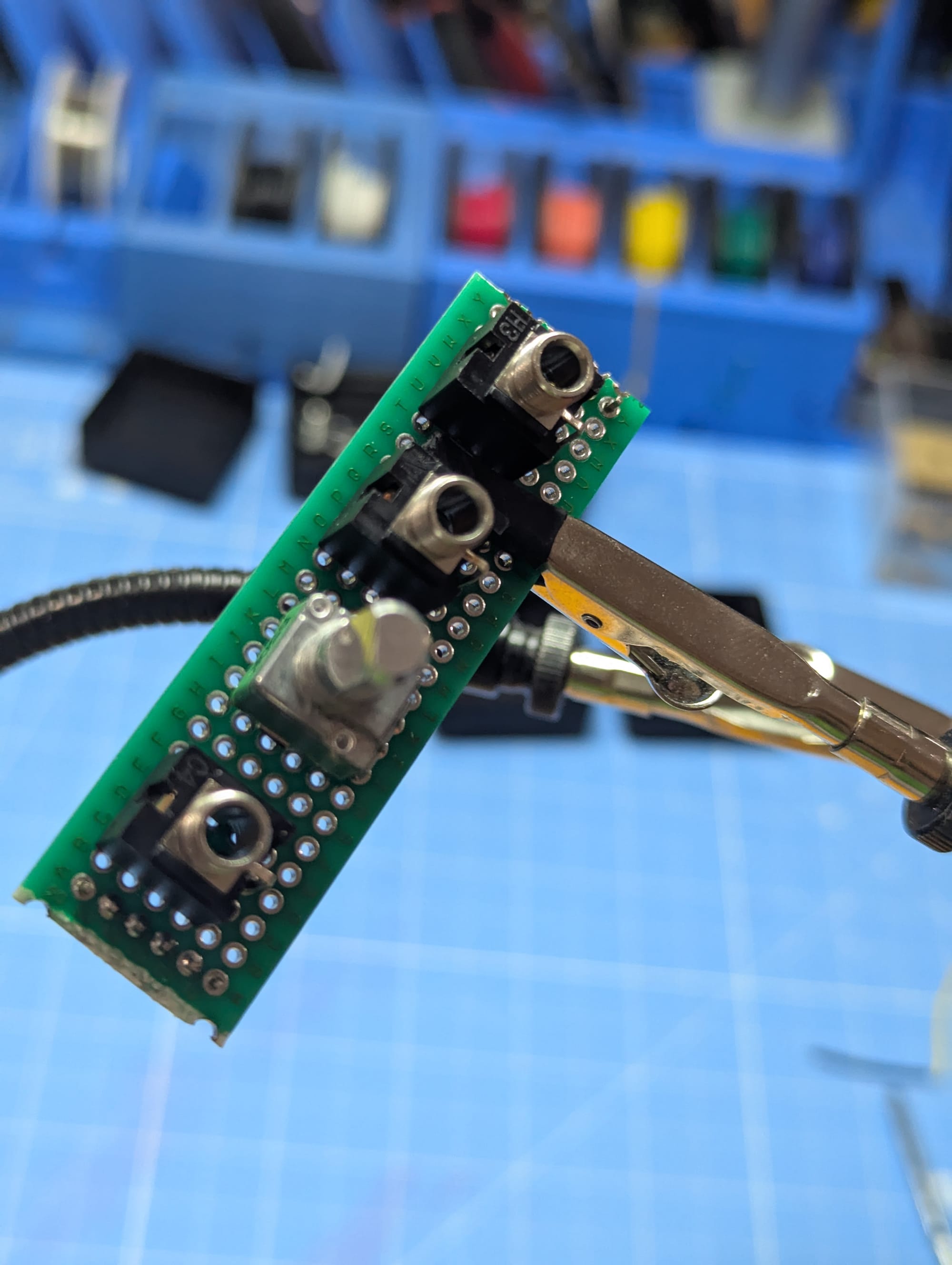
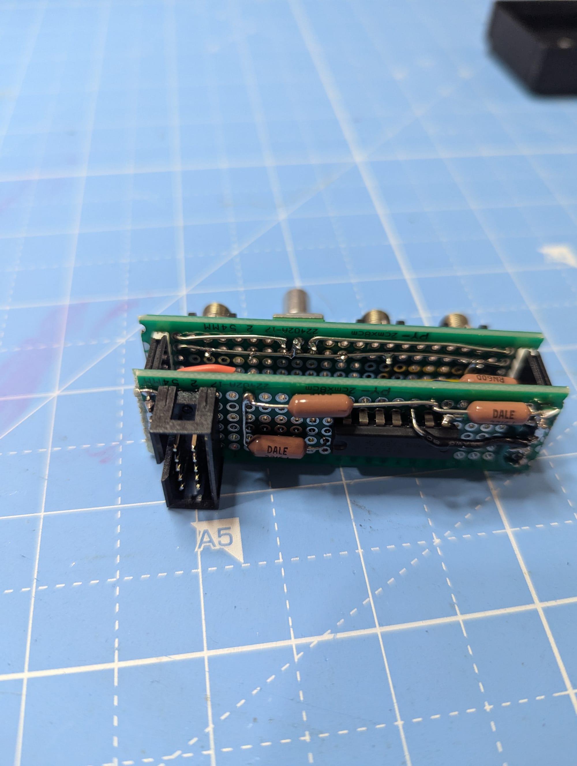
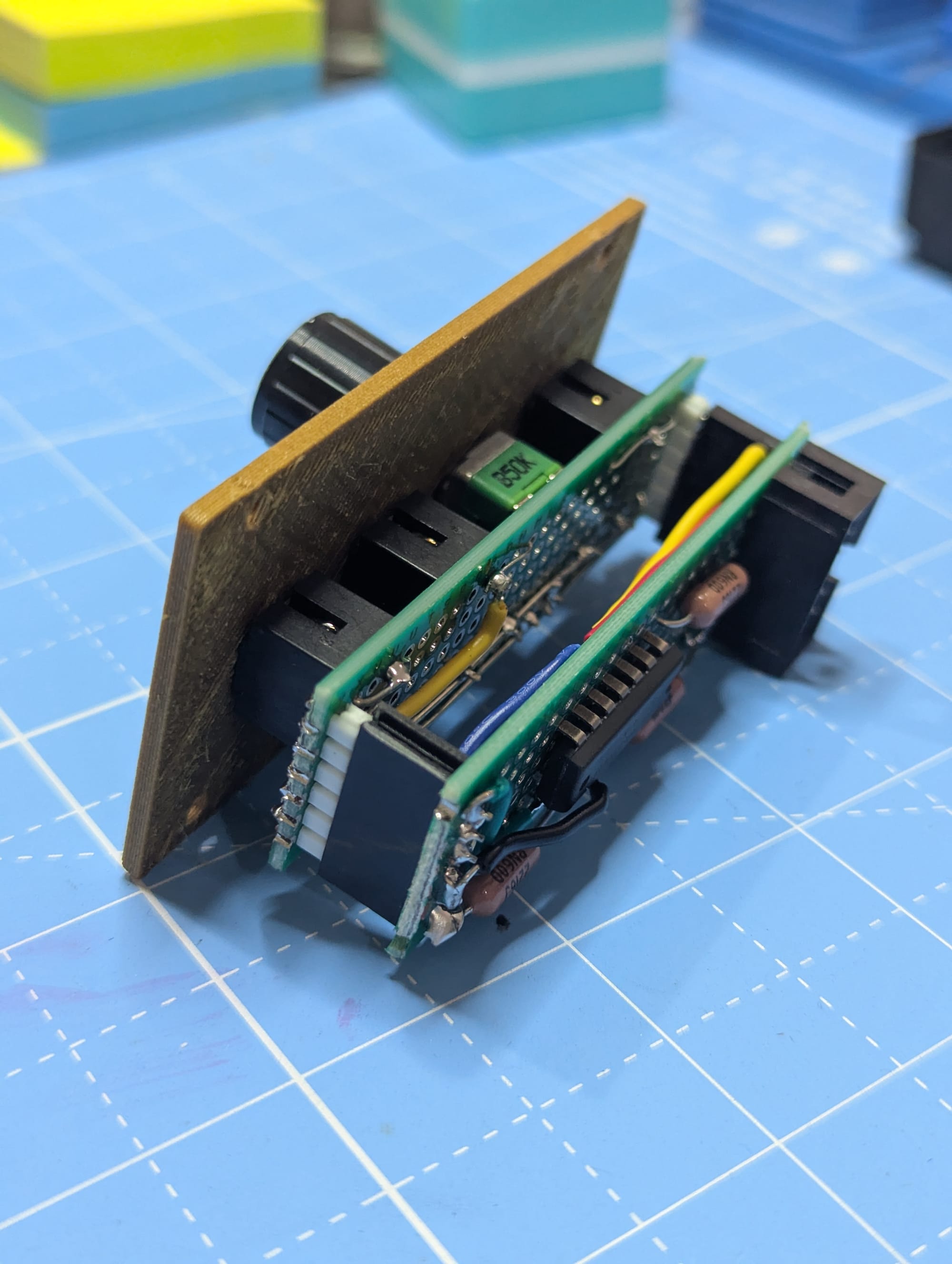
Naturally I had to split the circuit into two boards stacked vertically to maintain a reasonable width. This is pretty typical in eurorack design so no big deal. We'll have one for the interface elements (jacks, knobs) and one that has the power header and op-amp package.
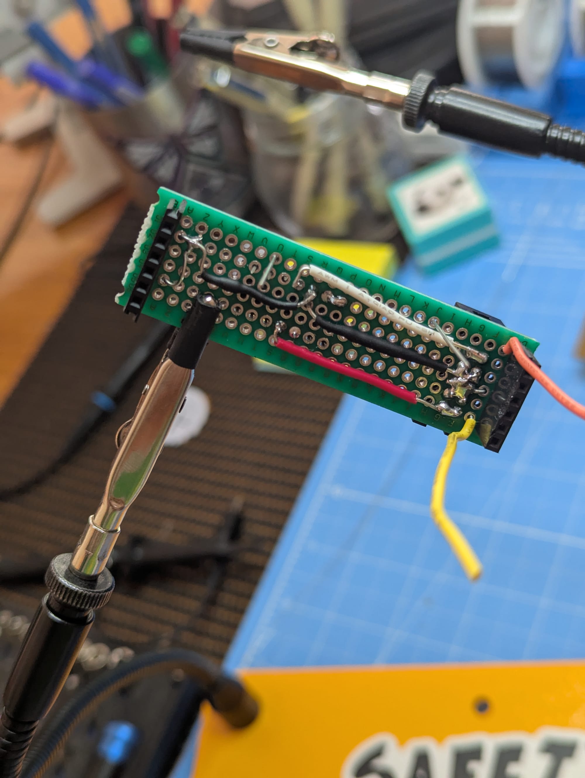
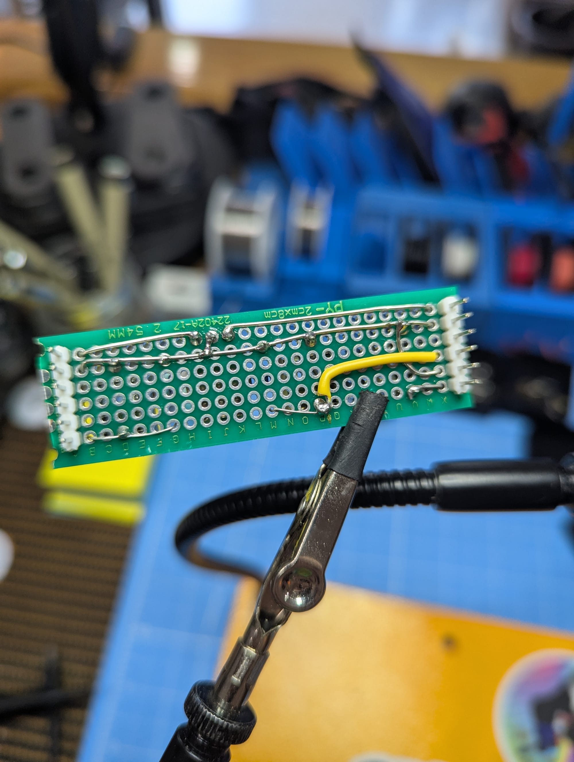
Once I got the interface elements placed on a board in an ergonomic way I had to start sketching out the "traces" for how everything would connect. This is definitely where you miss going through the PCB design process since the software to turn a schematic into a PCB has a lot of helpful features and error checking even if it does require a lot of set up. Instead I had to stare at this over and over after a couple context breaks just to be sure everything was right. Once the soldering started going back and fixing any mistakes would be really unfun so I did not want to beef it in the planning steps.
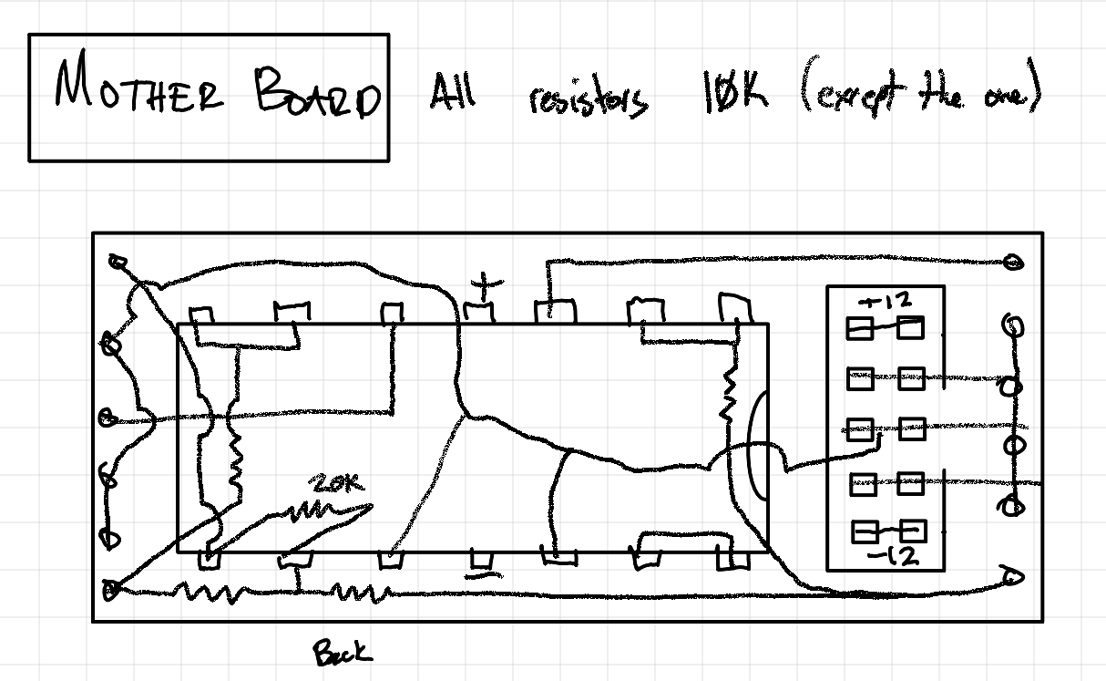
One thing I was super worried about getting the pins that connect the boards correct. It felt like it would be so easy during this phase or the building phase to forget what side of the board I'm looking at for any given node and put something in the wrong spot. Fingers crossed!
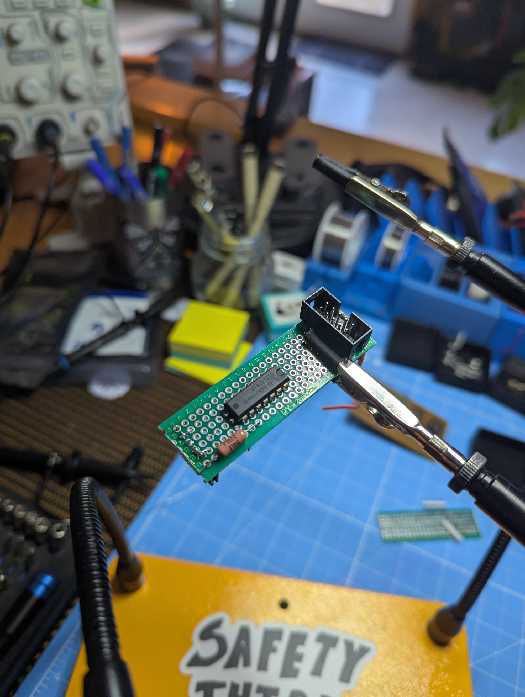
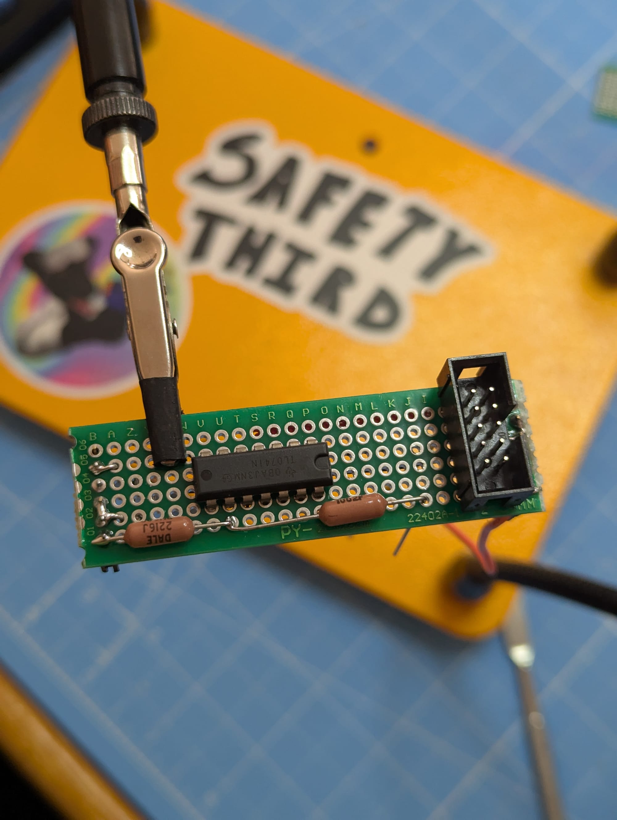
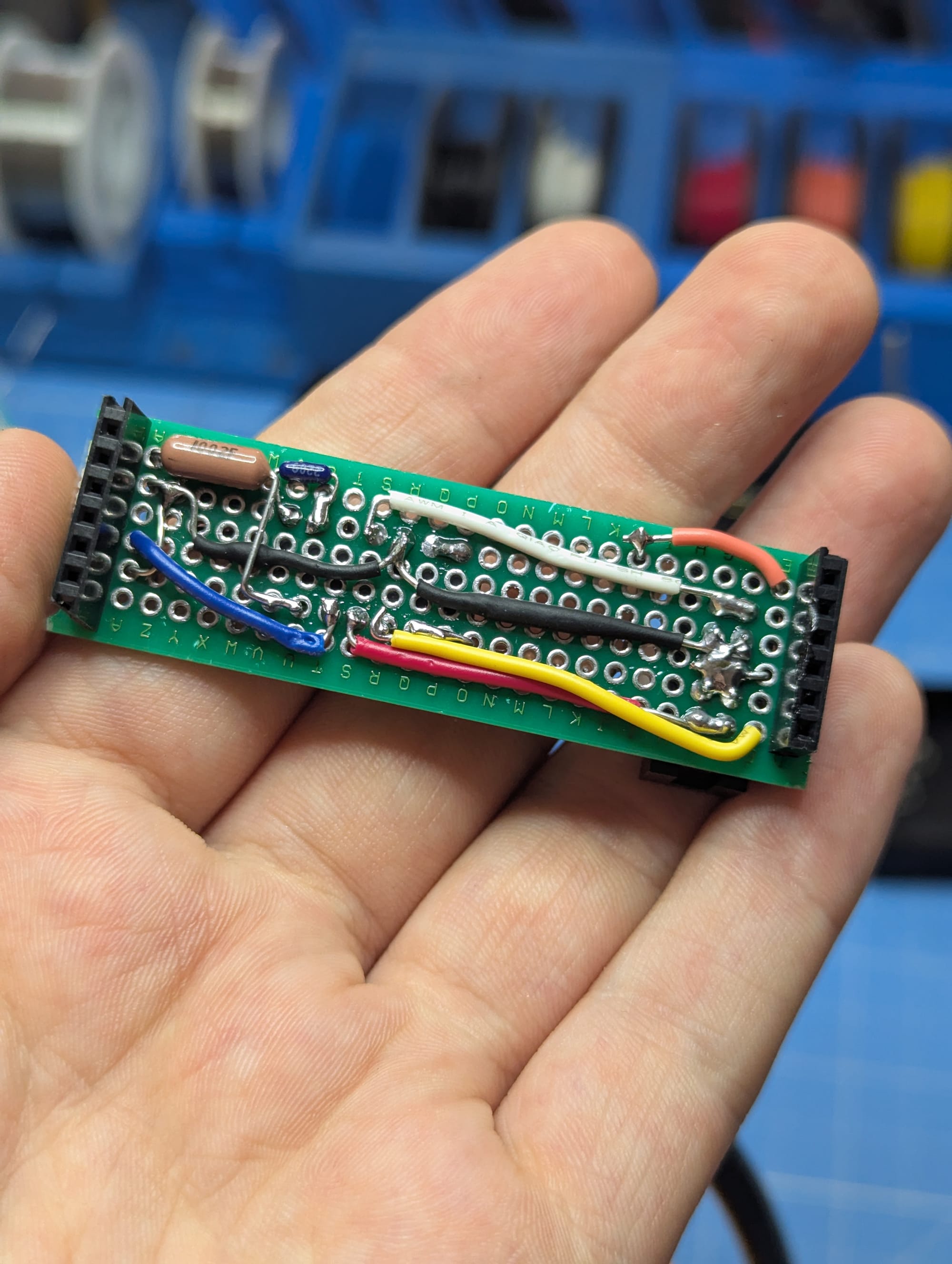
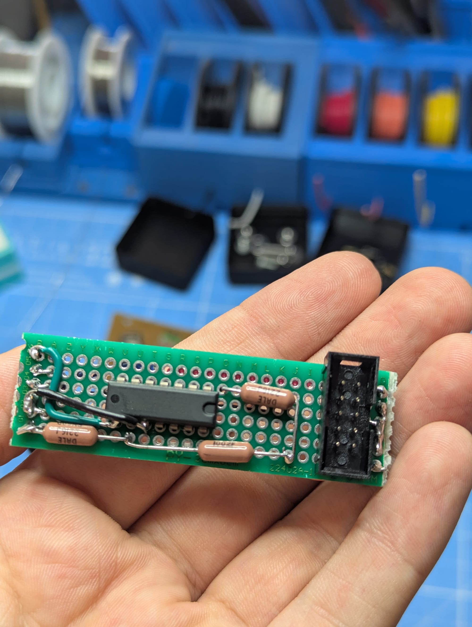
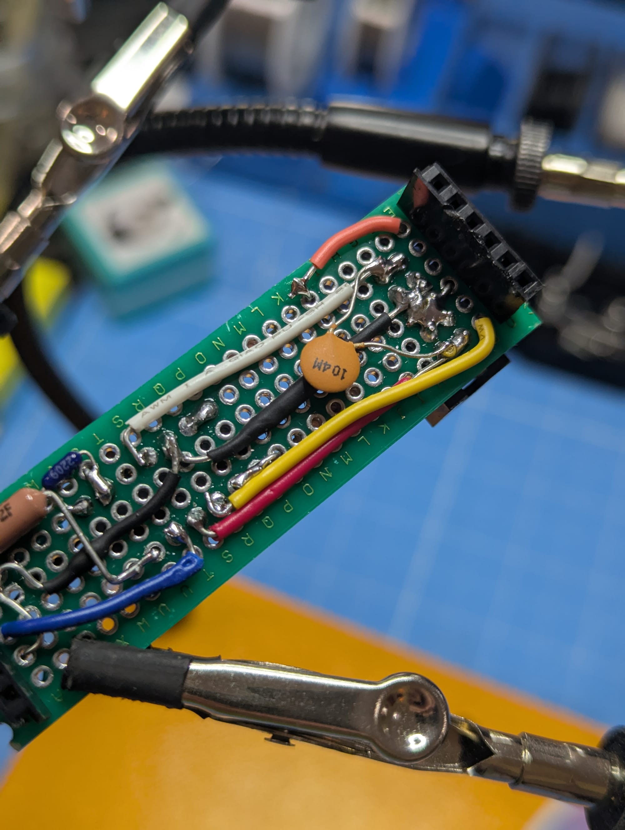
Main board wired up! Onto the interface board, luckily much simpler.
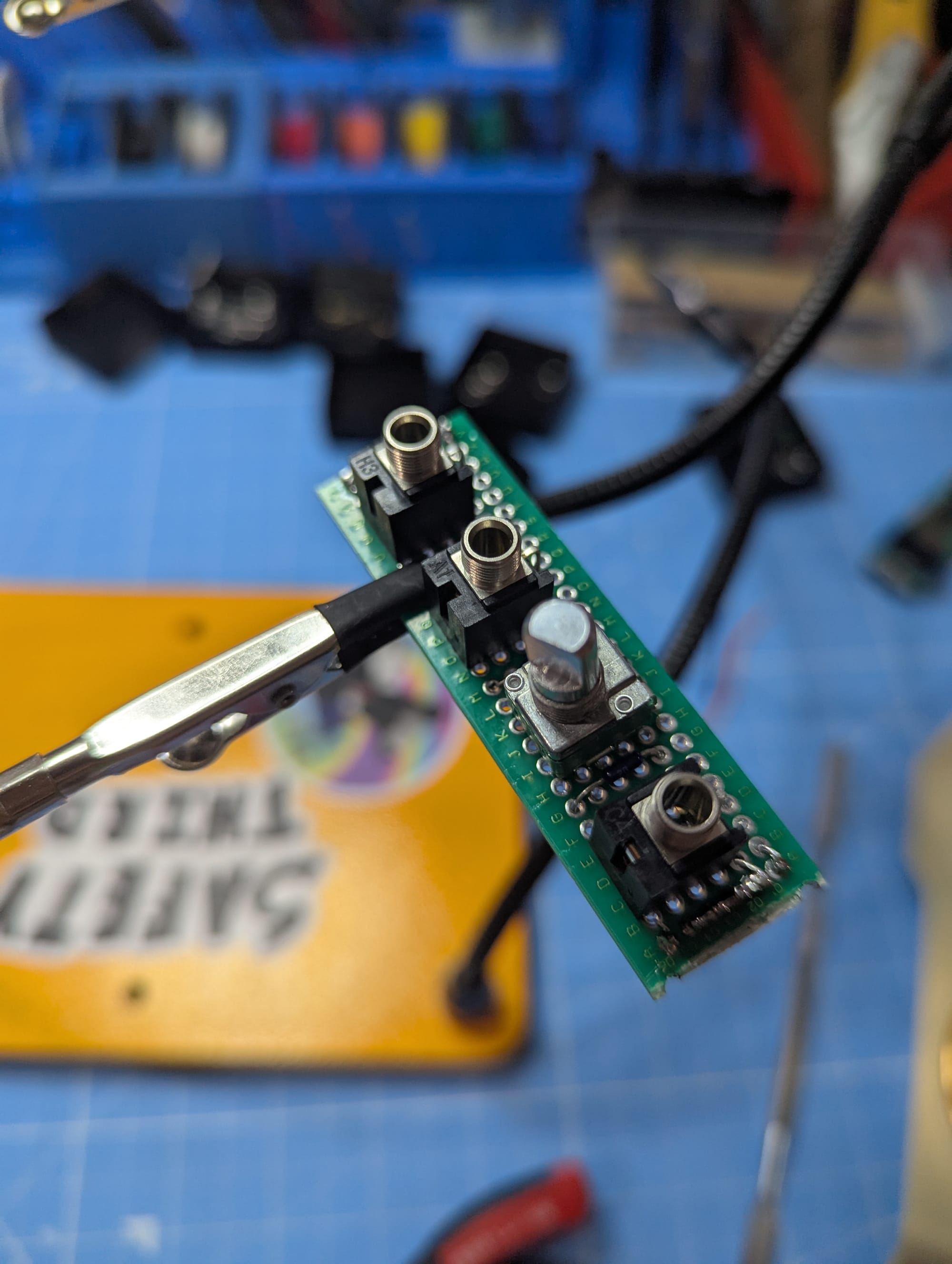
I almost did forget a power conditioning capacitor, quickly added that and smooshed the boards together:
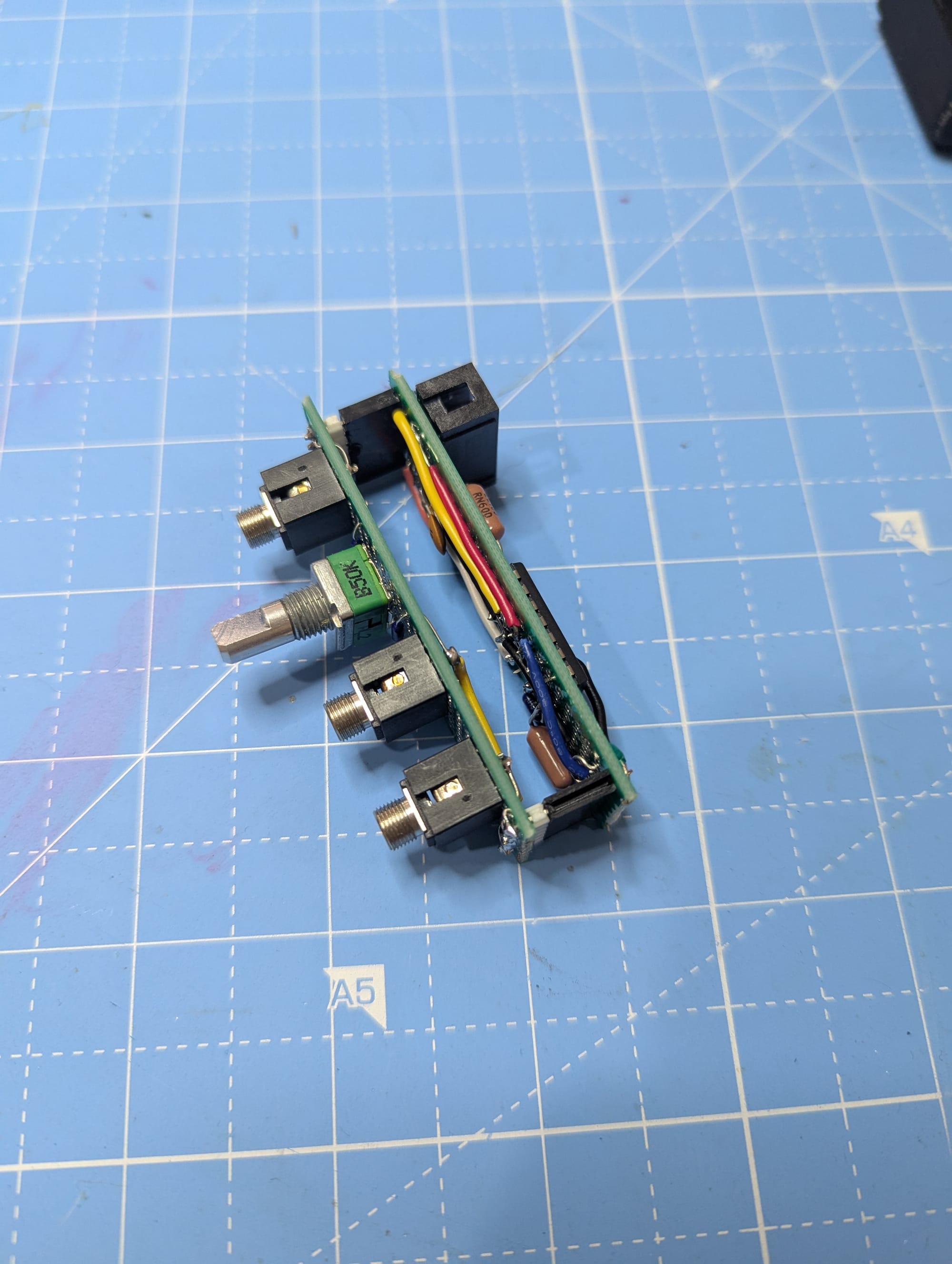
For the faceplate I just quickly got something drawn up in openSCAD
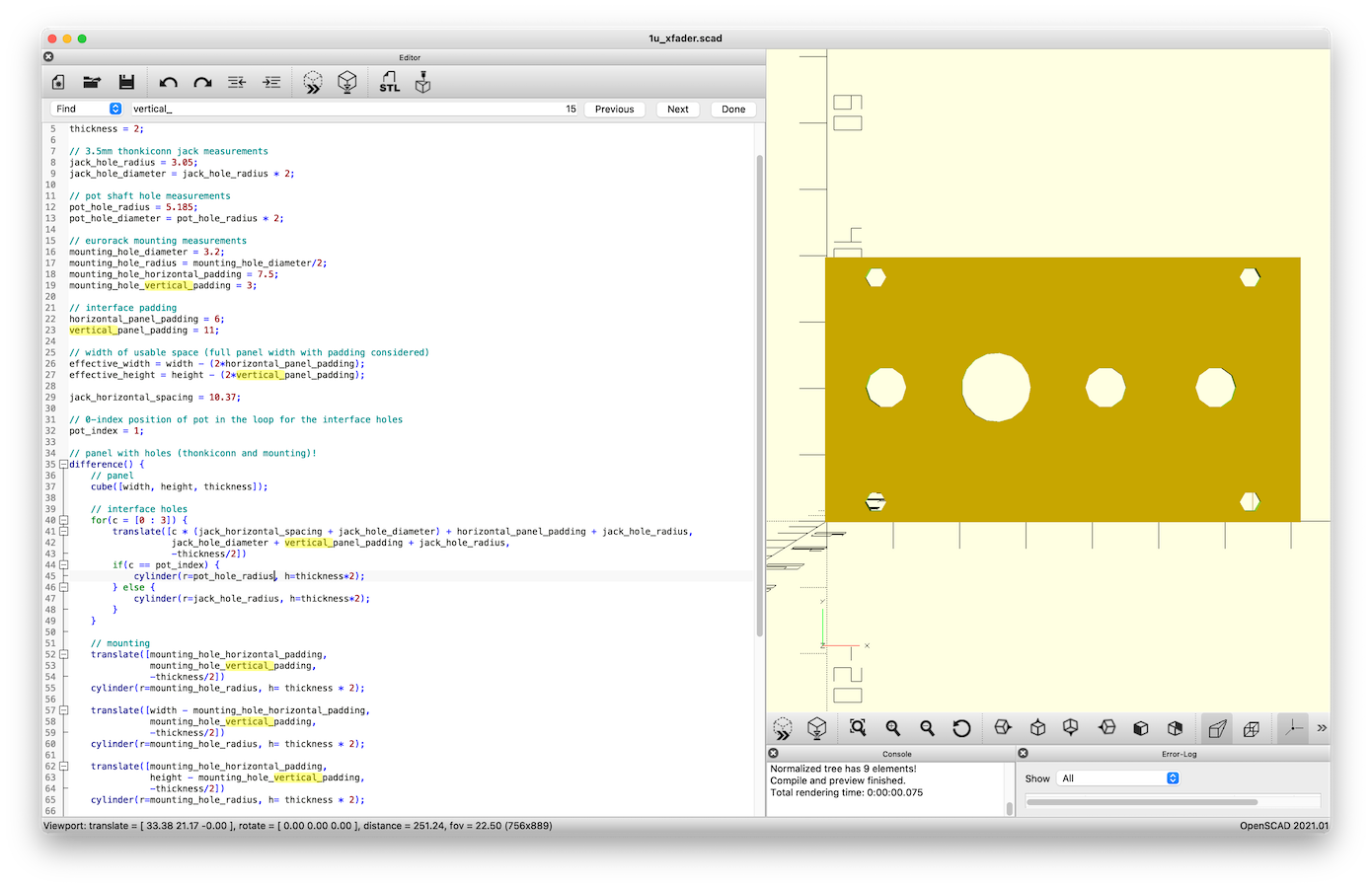
and after a few iterations to nudge everything in the right place....
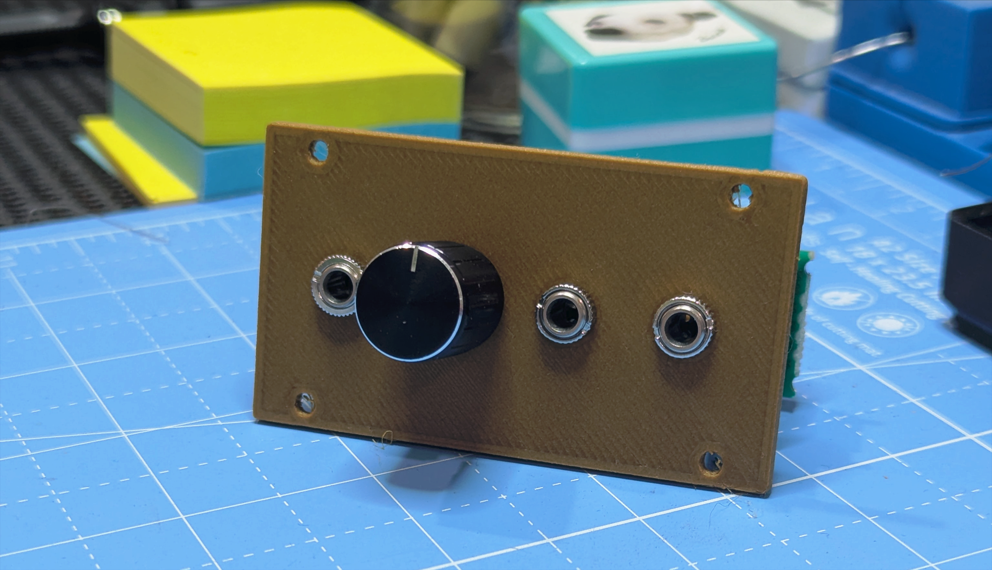
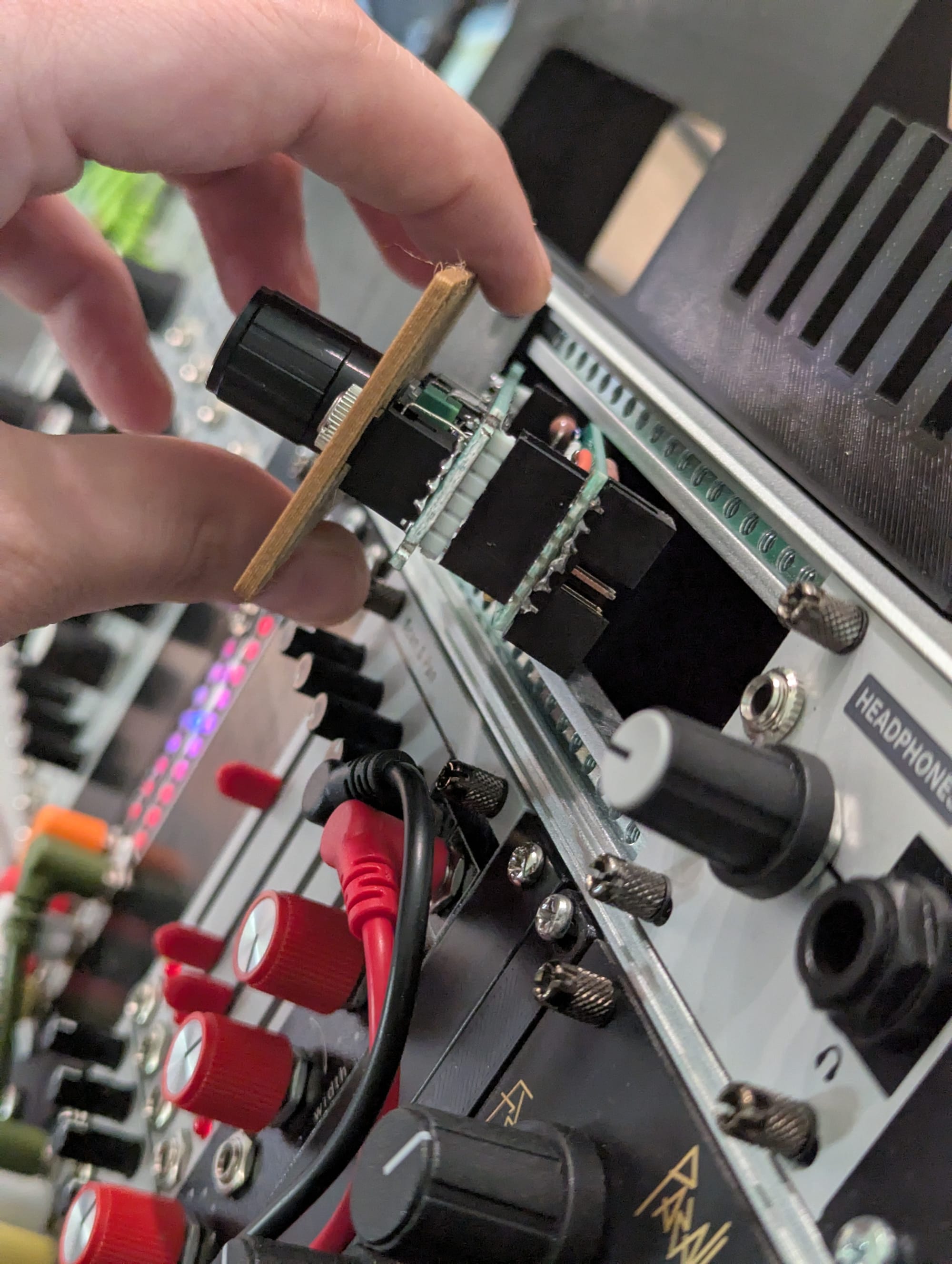
It fits! It powers on! It works! Here's me crossfading between a snare and a kick drum as proof of life.
Probably would have been better to use sounds more distinguishable by waveshape or at least zoomed out on the scope a little whoops
Now I just need to make like 2 more...