Voltage Controlled Video Looper
Designing and building an LZX/Eurorack compatible video clip player and looper
I have been long putting together an LZX video synth and with the eventual arrival of my TBC2 module I finally had a reliable way to send external video into the gear. While I initially had a lot of fun with an old VCR and thrift store VHS finds....well, it turns out having to rewind all those VHS' kinda sucks, hah. Then once they are rewound you have to fast-forward them to the actual content you want to see or at least past all the trailers and FBI warnings.
want to go straight to the code?
check out the repo here
So I decided I wanted to design and build a dedicated video player to be able to loop through smaller chunks of more curated content using a Raspberry Pi 4. My initial sketch looked like this:

The main features I laid out were:
- 12 Banks of 12 Clips
- use a 7 segment display to show current Bank & Clip indexes
- managed via a local web server/interface
- Radial Playhead to show progress of current Clip
- 6 Buttons
- Mode: toggle between random/sequential playing of the current Bank
- Prev: go to previous video in Bank
- Play: toggle play/pause of Clip
- Next: go to next video in Bank
- Hold: loop current Clip indefinitely (toggle)
- Shft: shift button. hold and use Prev/Next to switch Banks
It all seemed pretty doable from a high-level!
First thing I did was try and source the components for the 'Radial Playhead' and Segmented Displays just to make sure they were something I could find and work with reasonably. Of course, Adafruit had everything I needed, including the libraries and helpful documentation to take out a lot of guess work. I grabbed a 12 pixel Neopixel Ring for the Playhead and a 4-Digit 7 Segment Display for the Bank/Clip indicators. I would have preferred 2 2-digit displays as I sketched out, but they only had the 4-digit variety over there and it came included with a "backpack" to handle all the i2c matrix nonsense so it was a no-brainer. Once they all showed up in the mail I started plopping everything down:
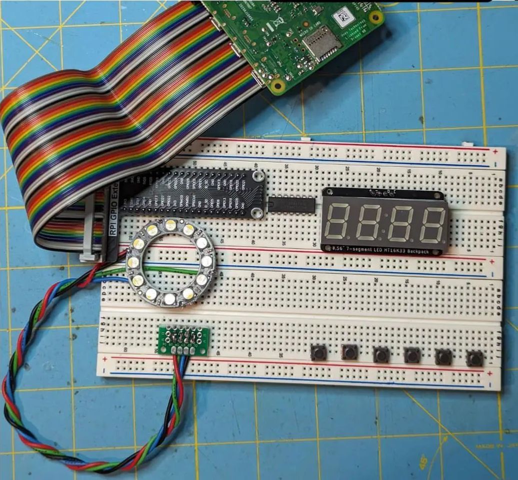
Not bad! I got all the main interface hardware on a breadboard and wired it up to the power and the Raspberry Pi. Which meant I had to get started on the actual software side of the project.
The first part of the software I went after was creating the web server/interface to manage the Banks and Clips on the machine. I was inspired by how norns used a local web interface for its own management and building a norns was also the last time I used a Raspberry Pi so it easily came to mind. Since I am not really worried about security as this is only accessible through LAN, I went with a simple flask app. It did take me a full weekend of working on/off to get all this work done, but I think it has all the features you'd want:
- Upload files from the computer accessing the web interface
- Download YouTube videos straight to a Bank
- optionally provide start/end timestamps to only download part of the video - Rename Clip
- Re-order Clip in Bank
- Delete Clip
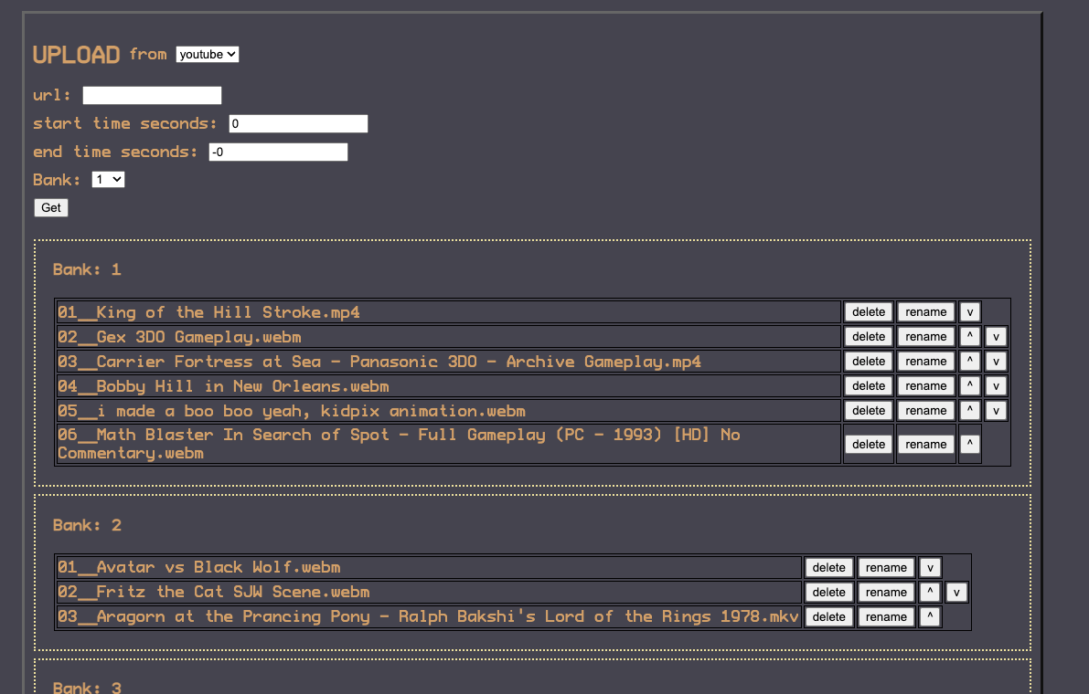
Once that was all done, I could move on to sorting out how to actually play and loop content on the Pi.
After searching around I landed on MPlayer because it seemed to have good documentation and had playlist support which I thought might come in handy as a representation of a Bank.
It took me a little bit to figure out how to manage MPlayer best from the python script that was my main Clip player application. Sparing boring tales of trial and error I ended up using MPlayer in "Slave Mode." This mode allowed me to send MPlayer commands via stdin, which is how I would issue the commands to go to the next clip, etc. Combining that with pexpect meant I could spawn a process of MPlayer in "Slave Mode" and issue it commands, then wait for and read responses while still handling button presses in the app code.
Once I finally was able to upload clips to the device via the web interface and play them with MPlayer, I could actually test the full content loop for the first time:
Once I had this proof of life, I could write the rest of the code to implement all of the features I lined out above – I was lucky to be able to include them all! The application code can be viewed here if you're curious to see how I accomplished that.
Back to the circuit! I had all the buttons wired up and their respective functions working in the software, but I still hadn't made this thing LZX/Eurorack compatible, i.e I had yet to add voltage control.
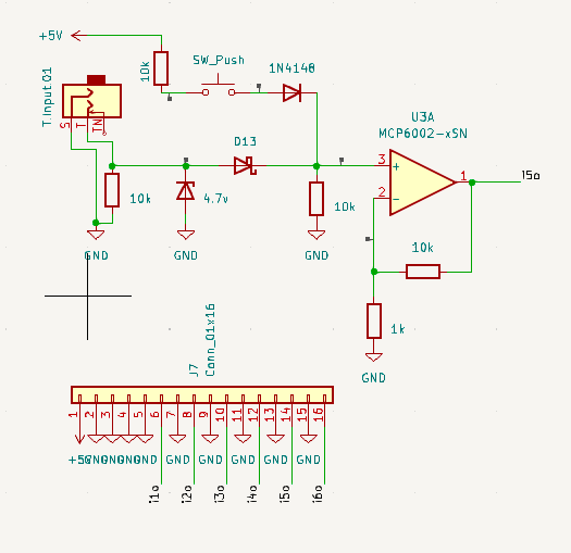
I quickly made a circuit for a voltage control input with my best attempt at negative voltage protection, over-voltage protection, proper impedance, and amplification.
The protections were to stop any damage occurring to components down line in the circuit or any GPIO pins on the Pi itself if any incoming voltage was outside a safe range. I added an amplifier to the end of this part of the circuit so that voltage as low as ~1v would be scaled up to something that the Pi GPIO would detect (>= ~3.3v). LZX format synths usually work in the 0-1v range which is what motivated this addition.
Just after the amplifier I added a single signal diode that will share a Cathode with a diode trailing the Button paired with the voltage input. This should create a passive logical 'OR' between the voltage controlled input and the button so that if they are activated at the same time the voltage doesn't stack. I could/should have added a high value resistor to ground at this same node but I think the internal pull down at the GPIO should suffice.

It should probably be noted that I'm a total novice when it comes to analog circuit design and there are probably better and cheaper ways to accomplish my goals in general, and especially in this case.
That voltage input was the last part of the circuit I need to move on to designing the PCBs! There was going to be one for the control board (where the buttons and voltage input circuits would be) and a "hat" for the Pi connected by a ribbon cable. I decided to use KiCad so I first had to convert my breadboard into a schematic with actual part footprints that could be brought into the PCB designer.
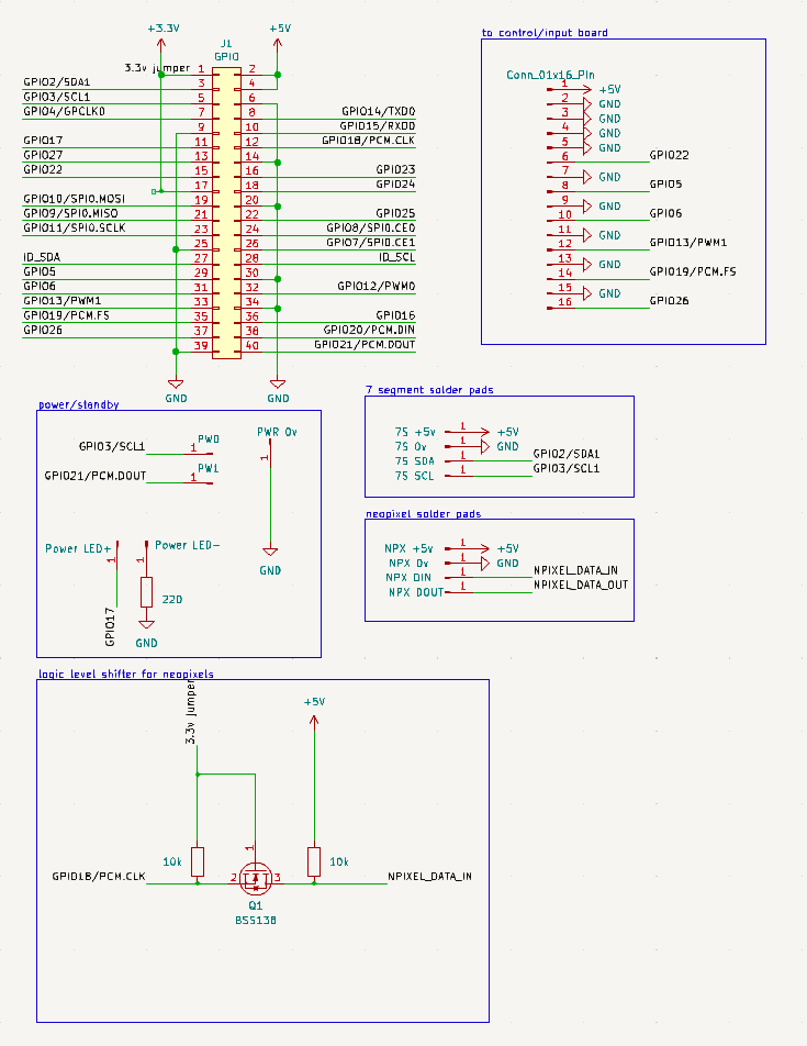
I did replace the quad level-shifter I had on the breadboard with a more discreet single level-shifter in the final schematic since I only needed the one.
Once that was done I could do the actual PCB layout and get them manufactured. This took a week or so per board so I had to do a little waiting.
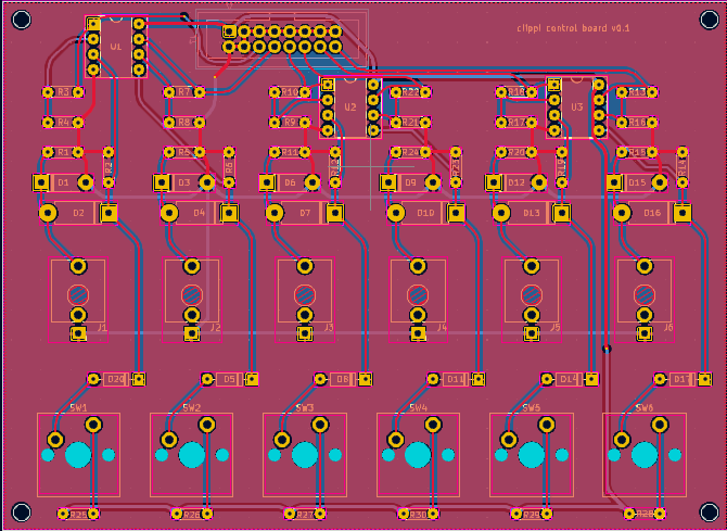
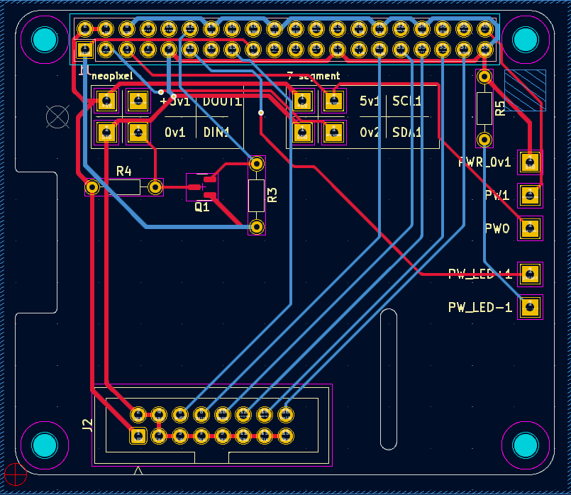
But they did arrive!
The first thing I did was solder up a control board and test it against the breadboard version of the Pi hat just to make sure that was working properly. I also did create a ribbon cable helper for the breadboard to help.
Now with all the circuitry and software pieces complete, I had to finally bite the bullet on making some kind of enclosure. I am novice enough at analogue circuit design, but this was an even larger uphill battle for me as I've never had the attention span to really learn Blender past the very basics, but I headed on as the plan was to 3D print the enclosure.
I started by making sure I could get a good fit for the pi and the control board, even that took more than a couple tries for me
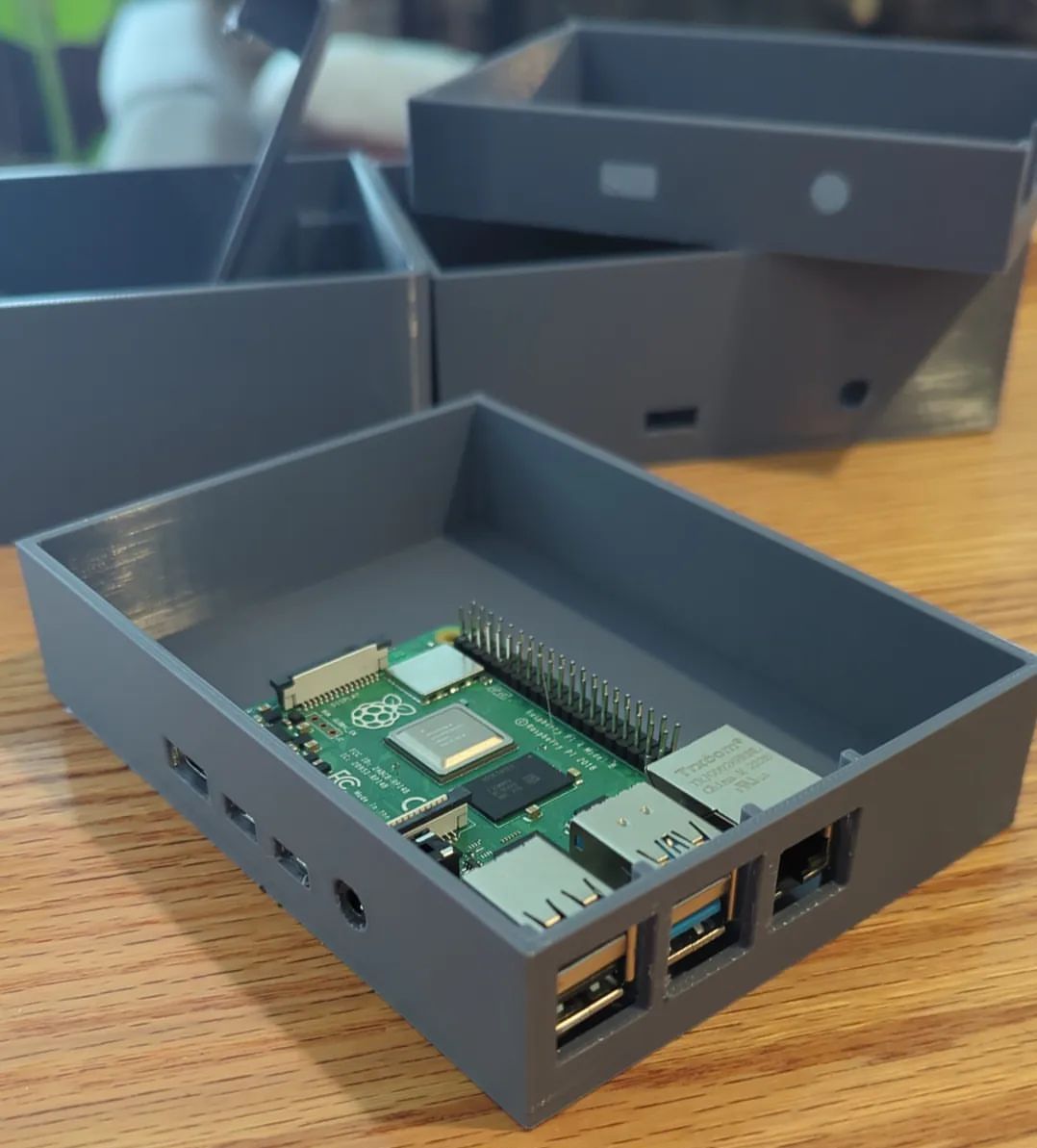
After much trial and error I eventually did end up with some kind of enclosure. I wasn't really that happy with it but I got it to the point where I could at least test fit everything. It was just so blocky and tall.
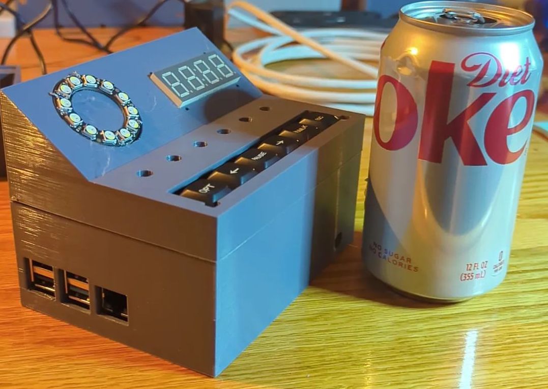
A big part of me didn't want to, but I took it back to the drawing board at this point. I really felt that after stumbling through Blender for a week to get here and picking up some knowledge I could make something better in a shorter amount of time.
The first thing I did was tilt the control board in Blender to try and get some vertical space back, I moved it up a bit as well.
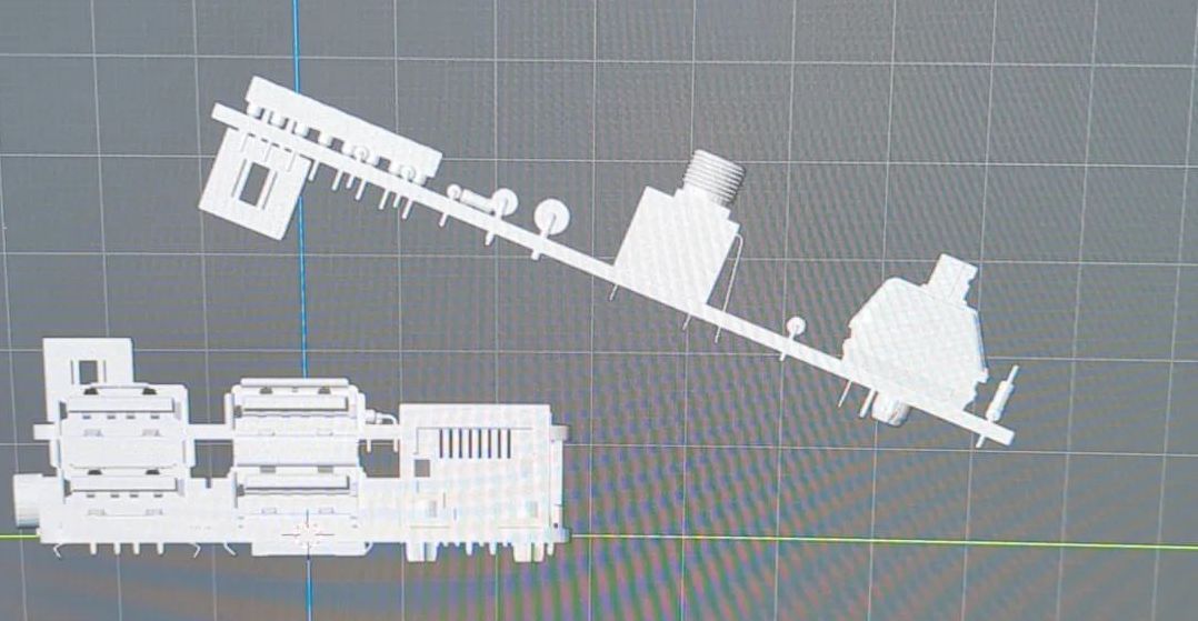
Then I brought in reference models for the Radial Playhead and the 7 Segment display and tried get a good position for those.

From there I just shaped a Plane to the profile of the new layout of all the components. After extruding that to the proper width I could start to make it an actual box, i.e removing inner volume and separating top & bottom. Then there was the busy work of punching all the IO and thread holes... As I predicted it was not long before I had something I was much happier with.
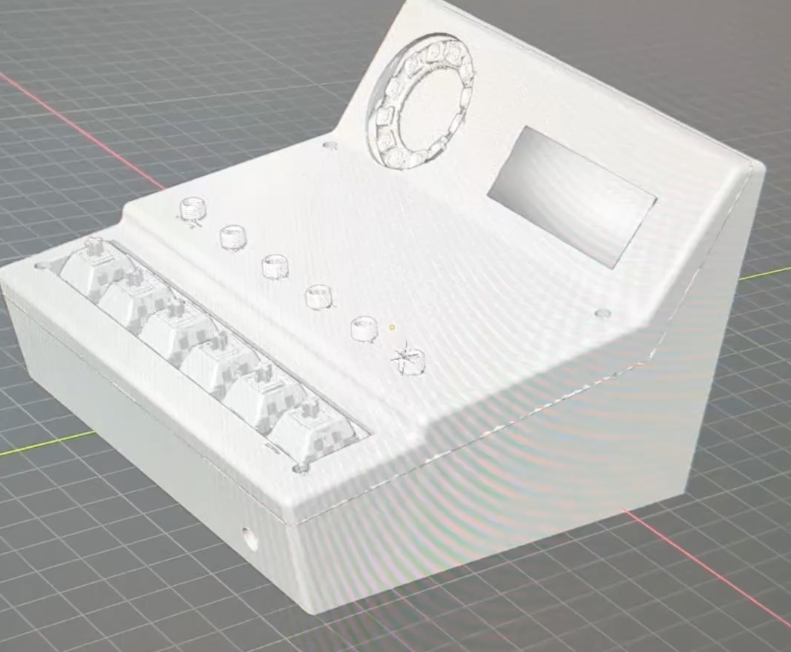
Some lightly rounded corners went a very long way but I think the overall shape is much more pleasing and interesting now as well! It also come out pretty decent in the print!
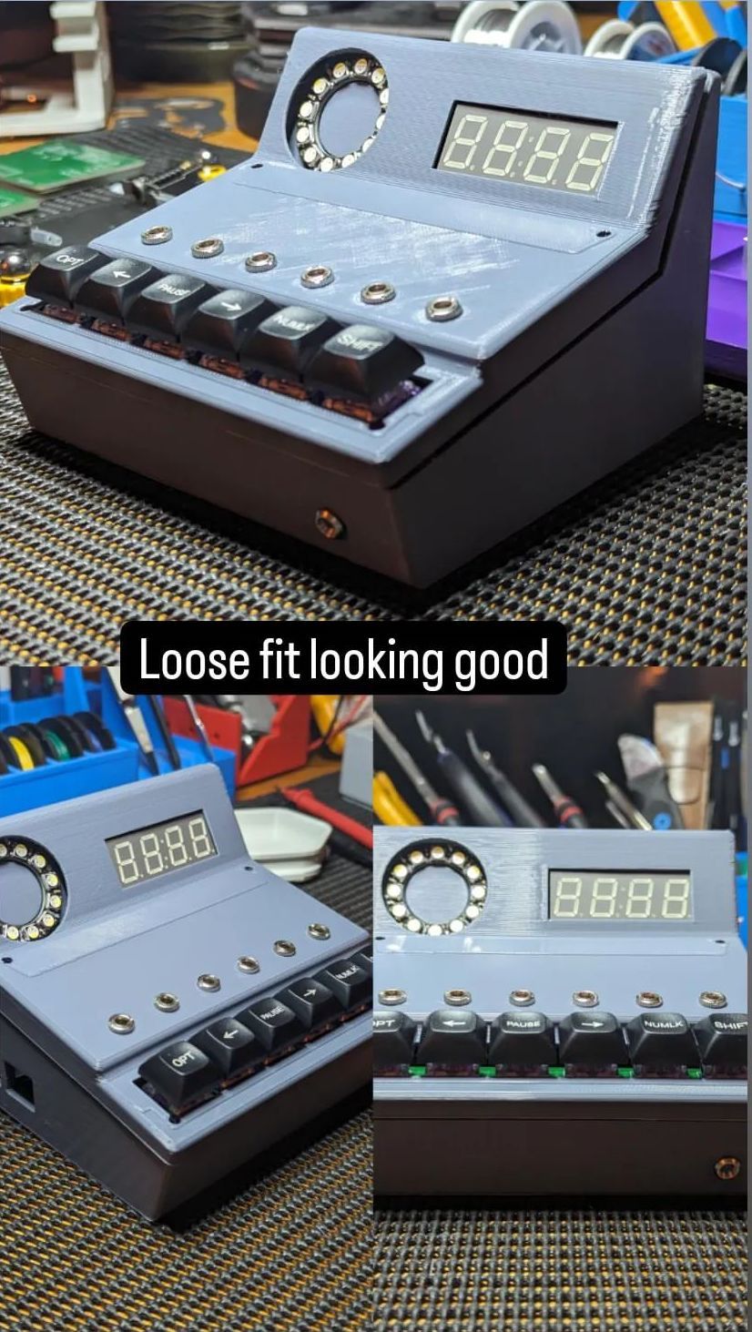
Now that I had an enclosure I was more proud of I could move on to adding the threads and wiring everything up. Most of this was pretty simple...the one thing that I would like to change in another iteration of this enclosure is the 'captive' Radial playhead, though. At the moment you have to solder the Playead wires after they are already routed and connected on one end, just not ideal.
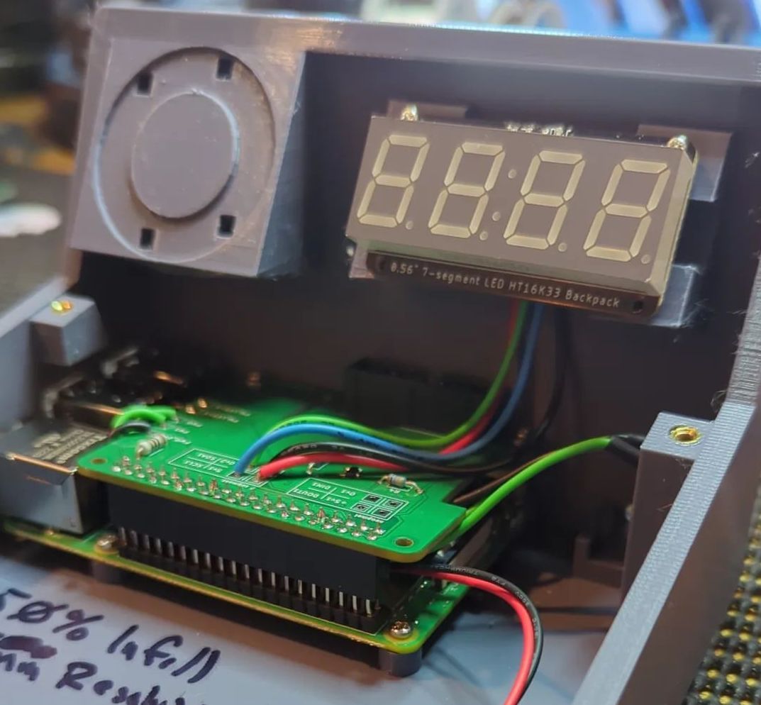
After wiring everything up I could finally turn it back on! Looking prettttyyy good.
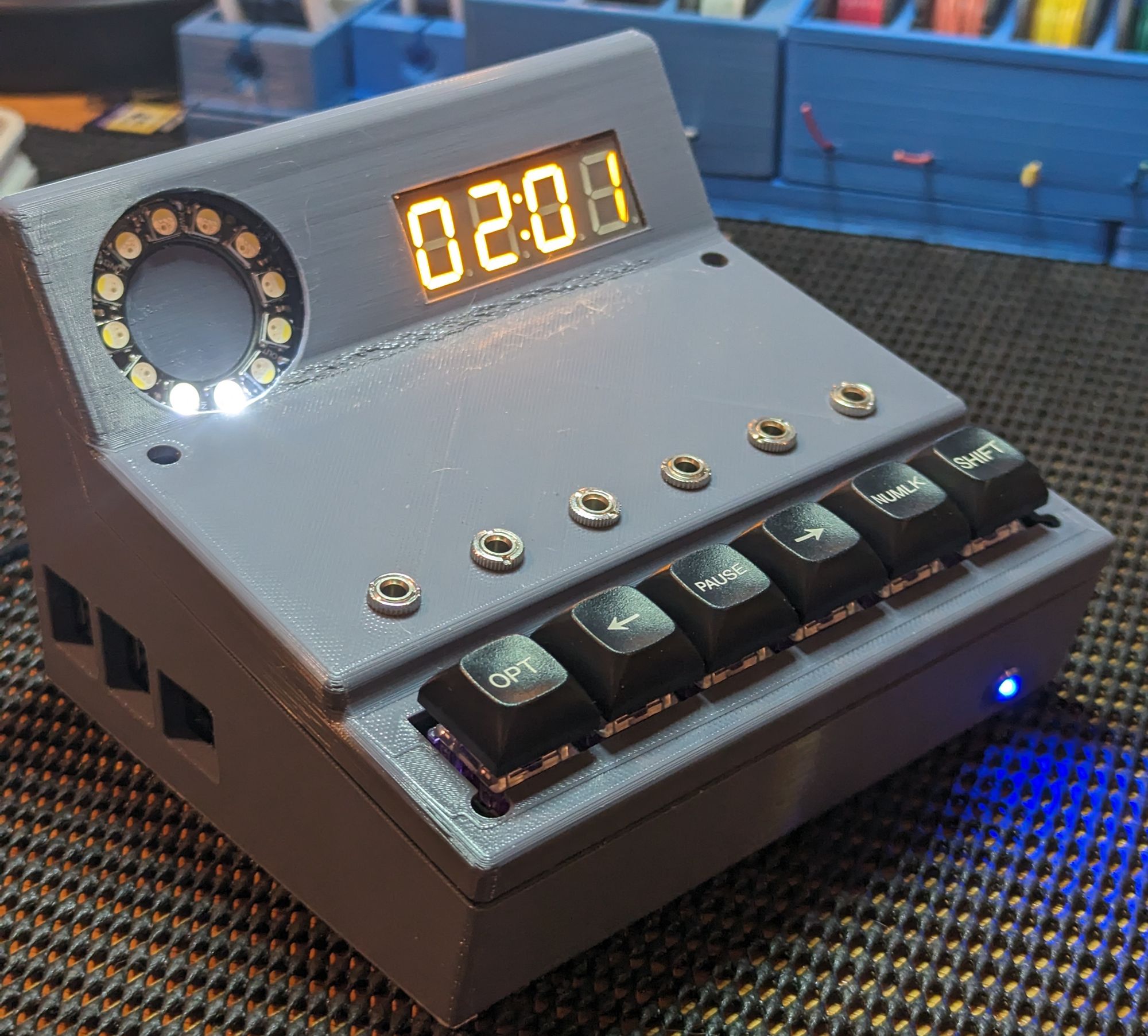
This was my very first time taking a circuit/gizmo idea from literal sketch to working "product." I've never completed a real schematic before in proper software and definitely hadn't designed and gotten my own PCBs milled. The whole Blender process was such a big hill to climb in its own right.
I used to look at schematics and PCBs with total awe, thinking there would never be a way I could understand let alone make something like that. This feels incredibly cool.
